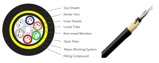
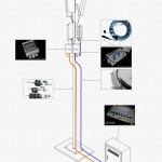
ADSS cables. All-Dielectric Self Supporting cables. The All-Dielectric Self Supporting (ADSS) cable is a completely non-metallic structure in which the tensile load bearing elements are integral within the circular design of the cable – usually in the form of aramid yarns or stranded glass reinfroced plastic rods.
The structure of ADSS Cable
- Typically a loose tube cable design
- Designs are application specific
The Applications of the ADSS Cable
– Cable supports itself
- No external support or messenger wire – Uses new and existing right away
- Distribution or Transmission Lines – Designed to specific weather conditions
- NESC Light, Medium or Heavy Load
The Advantages about the ADSS Cable
- All-dielectric construction
- Eliminates bonding & grounding
- Live power line installation
- Lower costs
Key Specifications for ADSS Cable
- Maximum span distance between poles, Longer spans require more cable strength
- Installation sag: typically 1.5%. Less sag requires stronger cables
- Line voltage: Distribution: Use HDPE jacket span / Transmission: Evaluate line voltage/spacing compatibility, HDPE or track resistant jacket
- Maximum weather loading (wind, ice, safety factors, etc): Higher winds or thicker ice requires stronger cables / Can use location to determine loading per NESC.
- Fiber count: Higher counts (>72) increase the cable diameter: Larger cable diameters have more weight & carry more weather loading
- No of fibers per tube
- Maximum sag restrictions: Any clearance considerations / Restrictions may require a stronger cable
Key Information Needed for ADSS Cable Quotation
- Fiber Count
- Maximum Span Distance
- Weather Loading: NESC Light, Medium, Heavy or Other
- Line Voltage (kV) if transmission lines are used.
– System voltage worksheet required for > 69kV
– Needed to consider dry band arcing and corona resistance
Key Information Needed: Assumptions can be made if not specified
- Jacket Configuration (1 or 2): 1 likely will be assumed
- Initial Installation Sag? 1.5% is typical
Additional information to consider
- Number of Fibers per Tube: 12f/t recommended for distribution spans up to 144 fibers, 4f/t recommended > 144 fibers
- Buffer tube preference for closure routing: Polypropylene < 144, PBT > 144
- Elevation changes?
- Vertical or horizontal sag limitations/clearance
- Pollution level – important in high voltage applications
- Structure type & load capability
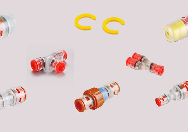
Microudct Connector
Straight Microduct Connector, Reducing Microduct Connector, End-stop Microduct Connector, Water/Gas Block Connector, Water/Gas Block Connector for Micro duct End, Micoduct Lock Clips
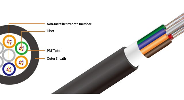
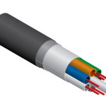
Loose Tube Type Air Blown Cable
Air lowing fiber, max. 288cores, for micro duct application
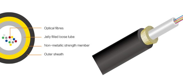
Central Tube Type Mini Air Blown Cable
Air lowing fiber, max. 24 cores, 4.0/4.4mm outer diameter, for micro duct application
