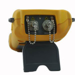
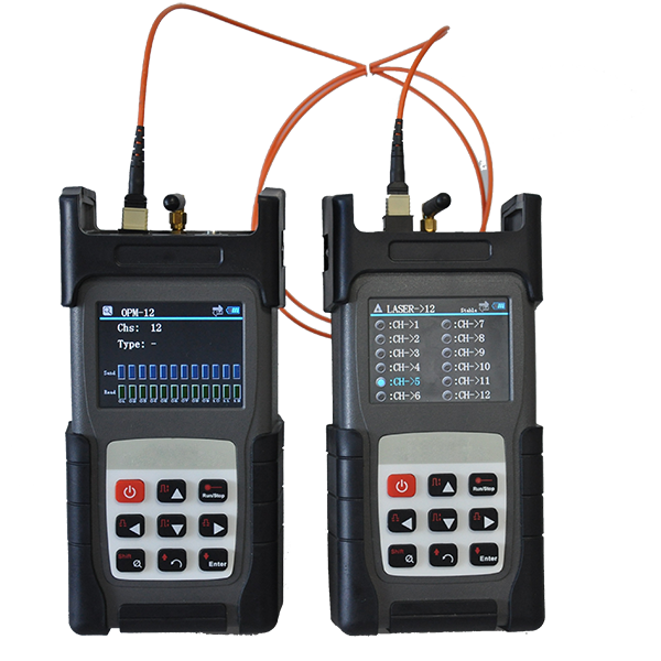
1. Use an ONT (Optical Network Terminal) / ONU (Optical Network Unit) Tester to determine if the ONT/ONU at the subscriber’s end is responding to downstream signals from the OLT (Optical Line Terminal). The Active ONT /ONUidentifier clamps on to 0.9mm buffered fiber, or 2mm or 3 mm jacketed fiber, or 2.0mm x 3.0mm drop cable, senses and reports the presence or absence of the 1310nm upstream response from an working ONT/ONU.
2. If an live ONT/ONU is detected, the fault is either an equipment or connection problem inside the subscriber’s end (most likely), or the ONT/ONU itself (less likely). Optical tests at the ONT/ONU are unlikely to resolve the problem.
3. If an live ONT is not detected, the fault may either be an ONT/ONU Failure or a fault in the PLC Splitter, distribution cable or drop cable connecting the feeder fiber to the subscriber.
4. In this case, disconnect the drop cable from the ONT/ONU, inspect and clean the fiber optic connectors on the drop cable and the ONT/ONU. If a damaged optical connector is found on the drop cable, replace, clean and inspect the new connector before proceeding. If a damaged optical connector is found on the ONT/ONU, the device likely will have to be replaced.
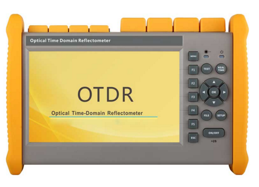
5. If connectors are clean and undamaged, check the downstream power level at the ONT/ONU using a PON Power Meter. Some OTDRs include a PON Power Meter integrated into their OTDR port, enabling immediate detection and measurement of downstream power levels at both 1490nm and 1550nm.
6. If the measured downstream power levels are acceptable, the problem is likely a failed ONT/ONU. replace the ONT/ONU, clean and reconnect the drop fiber, and verify the ONT/ONU synchronizes to the upstream OLT.
7. If the measured downstream power level(s) are not acceptable, the problem is likely a fault in the distribution or drop cable, or a fault introduced at the PLC splitter in the FDH (fiber distribution hub). In this case, connect a live PON OTDR to the drop fiber and initiate an upstream OTDR test using the out-of-band 1625 nm wavelength. To prevent disrupting service on the live PON, select an OTDR which prevents the user from initiating 1310, 1490, or 1550 nm OTDR tests when live traffic is present.
8. Some OTDRs also allow the operator to test only the customer fiber (distribution and drop), or to test through the splitter. Unless multiple customers are affected, the problem is most likely in the distribution and drop fiber, so testing only the distribution and drop fiber is a good bet.
9. Review the 1625 nm trace and event table to determine if there is a break or any excess losses or reflections in the distribution and drop fibers. If so, locate the problem location, repair the fault, then verify the fix by rescanning the fiber using the same 1625 nm test. To precisely pinpoint macrobends or breaks within a splice enclosure or access point, disconnect the OTDR and connect a Visual Fault Locator (VFL, a visible red laser). Enable the VFL and look for the point where the fault causes red light to escape from the fiber.
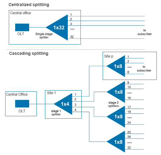
10. If no excess losses or reflections were identified in the OTDR trace, rescan the FTTx PON from the same location at 1625 nm using the “Test through Splitter” setup. This will provide a trace of the distribution and drop fibers with sufficient dynamic range to see through the splitter and measure the splitter loss. Since other probable causes have been eliminated, likely problems are a break or macrobend at the splitter, or the splitter has been disconnected from the distribution fiber. These will manifest themselves either as excess loss at the splitter, or as the fiber end being detected at the splitter. Repair the fault, then verify the fix by rescanning the fiber using the same setup.
11. Once fiber restoration is complete, verify the proper downstream power levels are available at the end of the drop fiber, clean and reconnect the drop fiber to the ONT, and verify the ONT synchronizes to the upstream OLT.
By Michael Scholten, AFL
