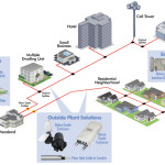
Insertion loss tests are primarily used to test FTTx PONs (Passive Optical network) during installation. Insertion loss testing may be performed on individual fiber segments as they’re installed (e.g. test feeder fiber from Central Office (CO) to Fiber Distribution Hub (FDH), test distribution fiber from FDH to AP, or test drop fiber from AP to subscriber’s home). An end-to-end insertion loss test may also be performed on the FTTx PON after it is partially or fully installed (from CO through feeder fiber, passive splitter, distribution and drop cable to the AP or customer’s premise).
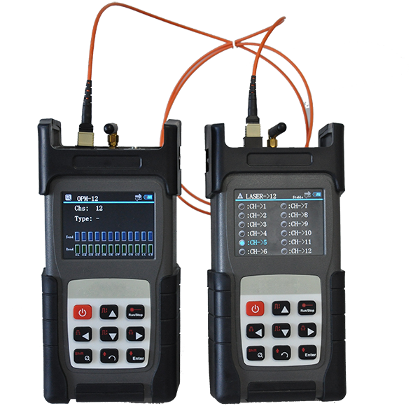
A stable optical light source and an optical power meter are required to measure insertion loss. Access to both ends of the fiber-under-test is required. Consequently, this is typically an out-of-service test. To measure loss, received power at the far end of the fiber-under-test must be compared to transmit power injected into the fiber at the near end of the fiber under-test. To simplify loss measurements, the power meter is initially connected to the source with a short patch cable and the source power level is measured and stored as the 0 dB reference level for that wavelength. Since the source’s output power levels and the power meter’s detector response are different at each wavelength, the power meter must be referenced to the source at each test wavelength.
Once the source and power meter have been referenced at each of the test wavelengths, the source—with the reference jumper still attached—is connected to one end of the fiber under test. The power meter is connected to the other end of the fiber-under-test. Received power level is measured and displayed. More conveniently, the power meter can compare the received power level to the stored reference, directly displaying optical loss in dB.
Simple power meters measure power at only one wavelength at a time. To make loss measurements at multiple wavelengths, the source must be configured for each test wavelength in turn. At the same time, the power meter operator must select the appropriate wavelength at the power meter so the correct detector calibration factor and reference level are applied. This is both time-consuming and error prone, as it requires coordination between the source operator on one end and the power meter user at the other end of the fiber-under-test.
To reduce test time and eliminate this potential for errors, FPM3 support twin function, it includes Wave ID. A Wave ID source alternately transmits light at each wavelength. A Wave ID power meter automatically synchronizes to the received wavelengths, eliminating the need for source and power meter to be manually switched between wavelengths.